Failure Analysis Process
Failure Analysis Process
A failure analysis investigation can accomplish many goals, but typically the goal is to determine how and why a metal component has failed or fractured during service. The outcome of the investigation is used to identify the following:
- Identify the root cause of a fractured component
- Identify the variable (or variables) that were responsible for the fracture
- Identity if the component was manufactured to the blueprint requirements
- Identify if the installation or service application caused or contributed to the fracture
- Identify if the service environment created corrosion that caused the fracture
- Identify if secondary metal working operations contributed to the fracture
Step 1
Background discussion with client
- Circumstances of in-service failure
- Background history of component, material and processing
- Population or statistics of similar failures
The background information provided by the client generally falls into two categories – all or none… If the component fails within the clients facility there can be a wealth of information that is provided that helps the investigation. Did the component fail during installation? 24 hours after installation? 1 year? Was a new material source was used, a new heat treat source was used, etc.
If the failure is a field return, there is typically much less information provided. Many times the field return is a warranty or claim situation where the user may or may not know the failure circumstances. The more information the better when trying to solve a metallurgical failure analysis.
- Was this a single isolated failure?
- If not, what is the frequency or percentage of failures from the original
manufacturing lot size?
The history will provide confirmation later in the investigation when reviewing the test results to identify the root cause of the failure. When the history is minimal or conflicting is where more questions can arise and additional failed sample are required (if available) to confirm the cause of the failure.
Time: ½ – 2 hours
Step 2
Visual and Stereoscopic Examination
The visual and stereoscopic examinations are important in identifying the following:
- Fracture Appearance
- Possible Fracture Initiation Site
- Identify possible secondary cracks
- Location of Fracture on geometry of part (ie. near change in section thickness, proximity to any welds, etc.)
- Presence of any corrosion residue
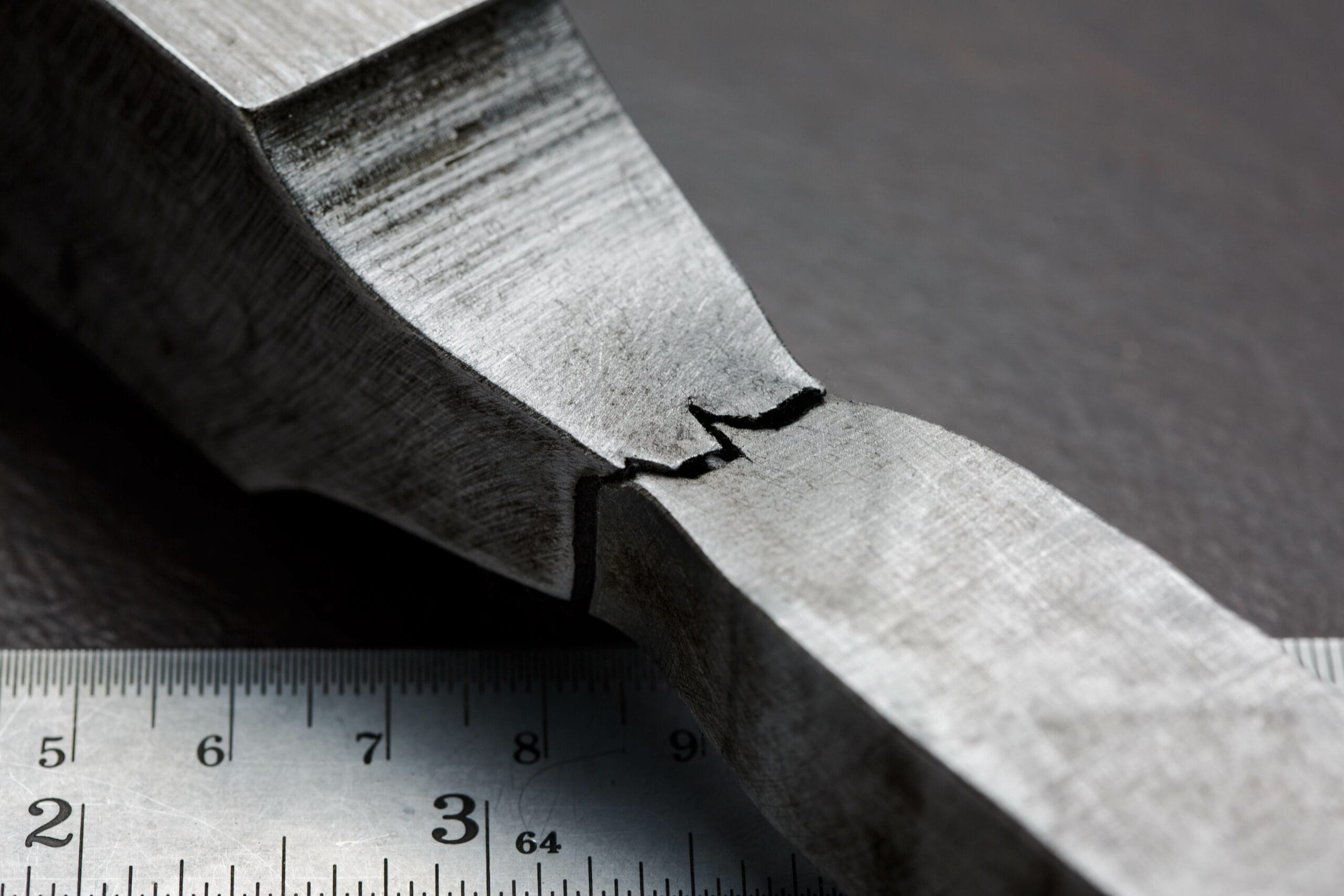
The as-received condition of the sample is documented as part of the visual examination using regular photography and close up macrophotography. Each step of the failure investigation is documented using photographs to help the reader see what the failure analysis expert is seeing. A stereoscopic microscope may also be used to examine the fracture surface. A stereoscope has magnifications ranging from 10X – 40X.
To help the next step of the investigation the component may have to be sectioned to permit the fracture to fit into the vacuum chamber of the scanning electron microscope (SEM).
Time: ½ hr up to 4 hours depending on the individual investigation
Step 3
Scanning Electron Microscopy (SEM)
The fracture surface is initially cleaned as part of the preparation for examination in the scanning electron microscope (SEM). The SEM uses electrons to view the fracture at high magnification in three dimensions. The key to the examination is to confirm the initiation site of the fracture that may or may not have been identified during the visual examination. The fractography of the initiation site may be completely different than the remainder of the fracture. The mechanism that initiated the fracture is the most important detail to identify. Once a crack has been initiated the fracture can propagate by another mechanism. It is easy to be fooled when doing fractography by a secondary propagation mechanism. The experience of the SEM operator and the engineer together as a team identify the fracture initiation site.
The SEM has a separate energy dispersive micro-analysis system that can identify the chemistry of any locations in the field of view on the SEM. Scattered electrons are counted by the EDS system to identify any elements associated with the targeted region. Specific locations of corrosion at high magnification can be targeted to help solve the source of the corrosion and the possible contribution to the component fracture.
Time: 1 to 4 hours depending on the investigation
Step 4
Sample Preparation (Mounting & Polishing)
The region identified during the SEM examination as the initiation site of the fracture is excised by cutting. SGS MSi has an extensive metallurgical preparation department plus a 10,000 sq. ft. machine shop that has eight band saws, two abrasive cut-off wheels and a wafering saw equipped with .012″ thick diamond impregnated blade. This varied capacity allows any hardness or any size sample to be removed for examination under the microscope. The sectioning phase can take many hours depending on the hardness, size and number of samples
After sectioning, the sample preparation procedure for microscopic examination requires potting or mounting the specimens in a mold (1″ to 1-1/2″ dia) with phenolic resin or epoxy powder. The phenolic or epoxy powder is heated under pressure so that all surfaces, cracks, porosity and gaps are filled in by the heated resin. After cooling, a multi-stage grinding and polishing operation is performed (by hand) through four different grits of sandpaper and then cleaned and polished through three more polishing stages to a final surface roughness of .05 microns – which is essentially a mirror finish. The mirror surface allows the microscope to examine edges and cracks on the optically flat surface. With poor or improper sample preparation the edges would be rounded and focusing at high magnifications is not impossible.
Time: 1 hr/specimen (exclusive of any saw cutting which can be from 1 – 4 hours additional time per specimen.)
Metallographic Examination
The mounted and polished specimen is examined on a metallurgical microscope at magnifications from 50X up to 1000X in both the unetched and etched conditions to identify all microstructural conditions associated with the fracture initiation site and adjacent regions. The examination in the unetched condition allows the engineer to examine the defect region for any evidence of secondary cracking conditions, oxides within the defect and the mode or shape of the defect or cracking (intergranular, smooth, etc.). All of the artifacts associated with the defect are photographed as evidence for the final test report. The unetched examination also allows for review of the non-metallic inclusion population and if the inclusions contributed to the failure.
After photographic documentation of all of the unetched microstructural conditions the specimens is etched using a chemical reagent specifically chosen by the engineer to reveal the microstructure of the base material. Examination of the defect region is performed a second time in the etched condition to identify all the microconstituents associated within the defect region. The microstructure at the surface, within the defect and at locations away from the defect are evaluated and photographically documented to provide evidence as to the cause of the failure.
Time: 2 – 6 hours
Report Preparation
The documented microstructural conditions and the all of the other metallurgical tests (chemical, tensile, hardness, surface roughness, etc.) are all collated, evaluated and a final report is created by the trained metallurgical engineer for the client who requested the metallurgical failure analysis. The final report is structured to provide:
- All provided background information
- A statement of the requested investigation by the client
- A list of the performed tests
- The itemized conclusions of the engineer as to the root cause of the failure
- All test results are presented as individual sections (with photographs)
- Recommendations (when requested by client)
Time: 3 – 5 hours
Peer Review
Upon completion of the report and a senior engineer from the SGS MSi engineering staff also reads the report as a “peer review” to perform the following:
- The report is read from client perspective to be sure findings are easy to follow and understand
- Proofread the entire report “cold” (no prior involvement) to determine if the report CLEARLY answers the client’s questions
- No typographically errors, run-on sentences, etc.
- Do photographs clearly explain the report
- Are any explanations missing or incomplete, is report easy to follow, do any photographs require additional captions, etc.?
Time: ½ – 1 hour
Total Time: Eight hours engineering time (minimum) is allocated per metallurgical failure analysis. Depending on the size of the component, whether corrosion is involved, multiple samples, etc., client conferences and possible conference calls (with their client). The total engineering time can be much larger.
Testing Charges: Additional $500 – $800 per investigation (metallographic sample sectioning & preparation, chemical analysis, SEM/EDS examination, tensile testing, hardness, and microhardness testing).
TOTAL COST (minimum) FOR METALLURGICAL FAILURE ANALYSIS = $3,000.00